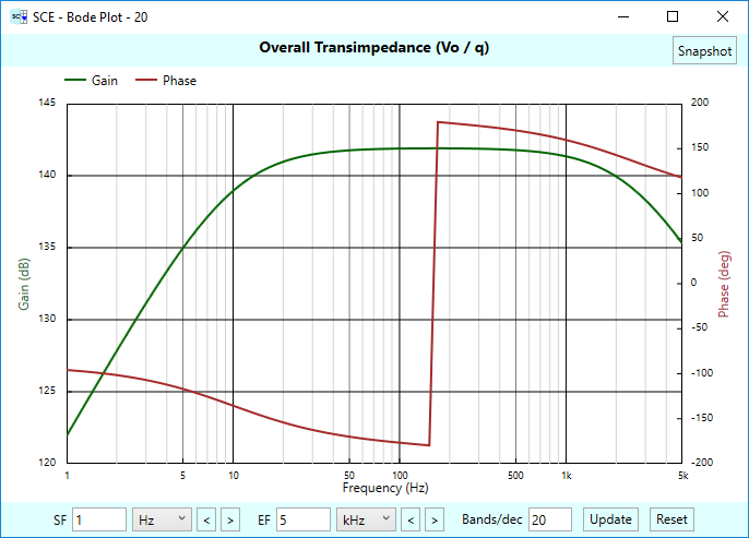
New functionality was recently added to Signal Chain Explorer that computes the minimum sensor power required to achieve a desired SNR (or ENOB) for a particular signal chain. This feature was originally experimental, but it didn’t take us long to decide to include it as an official part of the product. It brings valuable insight into the limits of any signal chain design, particularly when higher resolution is sought. With this feature you’ll easily see just how impractical it might be to seek high resolution — unless you take care in keeping noise down.
In Part 1 of this Short and Sweet article, we derive the formulas used to compute the required minimum sensor power, and along with it, the required input voltage and input current. In Part 2, we’ll see these formulas put to use in Signal Chain Explorer.
From SNR to Required Sensor Power
Here is the high-level diagram we’ll be working with in this article:
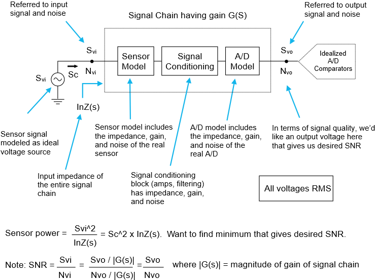
Suppose we have an input signal \(\displaystyle {{S}_{{vi}}}\) which is processed through a signal chain having a gain of \(\displaystyle G(s)\), an input impedance of \(\displaystyle InZ(s)\), and a noise voltage referred to output \(\displaystyle {{N}_{{vo}}}\). In the signal chain, we model the sensor input as an ideal voltage source, and then include a model for the gain, impedance, and noise of the sensor itself, followed by any signal conditioning circuitry, followed by a model of the gain, impedance and noise of any A/D converter included in the signal chain. We tack on a “ideal” set of comparators for the A/D, and it’s right at the input of these comparators that we measure the output voltage and the noise referred to output.
The goal is to find what minimum input voltage gives us a desired SNR (and by inference, a desired ENOB). From this minimum input voltage, if we also calculate the input impedance \(\displaystyle InZ(s)\) of the entire signal chain, the minimum required power delivered by the sensor can be found.
NOTE: By SNR, we really mean SINAD — where we total all sources of noise and distortion that can be root-sum-squared into a single RMS voltage. Even so, we’ll keep using the term SNR in this article anyway, but please think of it in the general sense.
One thing to realize from our high-level diagram: We can compute SNR two ways, (1) by referring the signal chain noise to input and computing \(\displaystyle SNR={{{{S}_{{vi}}}}}/{{{{N}_{{vi}}}}}\;\), or (2) by using the noise referred to output and computing \(\displaystyle SNR={{{{S}_{{vo}}}}}/{{{{N}_{{vo}}}}}\;\). As the diagram shows, these two forms are equivalent.
For convenience of calculation, we choose the first method, and note that
\(\displaystyle {{N}_{{vi}}}={{{{N}_{{vo}}}}}/{{\left| {G(s)} \right|}}\;\),
where \(\displaystyle {\left| {G(s)} \right|}\)
is the magnitude of the signal chain gain. Thus,
\(\displaystyle SNR=\frac{{{{S}_{{vi}}}}}{{{{N}_{{vi}}}}}=\frac{{{{S}_{{vi}}}}}{{{{{{N}_{{vo}}}}}/{{\left| {G(s)} \right|}}\;}}=\frac{{{{S}_{{vi}}}\times \left| {G(s)} \right|}}{{{{N}_{{vo}}}}}\)
Solving for \(\displaystyle {{S}_{{vi}}}\):
\(\displaystyle {{S}_{{vi}}}=\frac{{SNR\times {{N}_{{vo}}}}}{{\left| {G(s)} \right|}}\)
This equation tells us that if we have a desired SNR, and know the signal chain noise referred to output, and know the system’s gain, we can compute the required signal input voltage that will give us that SNR.
NOTE: You might wonder why we are taking the magnitude of the gain in the equations above. Realize that all voltages referenced are real-valued RMS voltages. Also realize that SNR is a unit-less measure, and since \(\displaystyle {{S}_{{vi}}}\) and \(\displaystyle {{N}_{{vi}}}\) are real-valued, then so must be the gain term. Since the signal chain gain is in general complex, we take its magnitude to make it real-valued.
As an aside, we’ll next show the formula for the required output voltage. It’s quite easy if you use the noise voltage referred to output:
\(\displaystyle {{S}_{{vo}}}=SNR\times {{N}_{{vo}}}\)
Okay, then. We are on the road to computing required power. But there’s one more piece to the puzzle. Suppose our signal chain has an input impedance of \(\displaystyle InZ(s)\). This is the load on our idealized sensor voltage source:

With this in place, we can finally talk about the required power delivered by the idealized sensor, using the power version of Ohm’s law:
\(\displaystyle {{S}_{{pi}}}(s)=\frac{{{{S}_{{vi}}}^{2}}}{{InZ(s)}}=\frac{{{{{(SNR\times {{N}_{{vo}}})}}^{2}}}}{{{{{\left| {G(s)} \right|}}^{2}}}}\times \frac{1}{{InZ(s)}}=\frac{{SN{{R}^{2}}\times {{N}_{{vo}}}^{2}}}{{{{{\left| {G(s)} \right|}}^{2}}\times InZ(s)}}\)
Power factor
We’ve denoted the signal power to be frequency dependent (using the Laplacian frequency term \(\displaystyle {s}\). Using \(\displaystyle s\to j\omega \) we can also write this as:
\(\displaystyle {{S}_{{pi}}}(j\omega )=\frac{{SN{{R}^{2}}\times {{N}_{{vo}}}^{2}}}{{{{{\left| {G(j\omega )} \right|}}^{2}}\times InZ(j\omega )}}\)
Since the sensor power is a complex variable, we can define the following four power terms:
- \(\displaystyle \text{Apparent}\,\text{power}=\left| {{{S}_{{pi}}}(j\omega )} \right|\)
- \(\displaystyle \text{Real}\,\text{power}={Re}({{S}_{{pi}}}(j\omega ))\)
- \(\displaystyle \text{Reactive}\,\text{power}={Im}({{S}_{{pi}}}(j\omega ))\)
- \(\displaystyle \text{Power facto}{{\text{r}}^{*}}=Sgn(Im(InZ(j\omega )))\times \frac{{\text{Real power}}}{{\text{Apparent power}}}\)
* The power factor ranges from 0 to 1, where 1 means all real (dissipative) power. But as a convention (unique to Robust Circuit Design), we also attach a sign to the power factor that helps describe the nature of the reactive part of power — if it exists. If the sensor load is capacitive, (meaning the imaginary part of the load is negative), we make the power factor negative. If the sensor load is inductive (meaning the real part of the load is positive), we make the power factor positive. We stress that this convention is ours alone here at Robust Circuit Design. Don’t be confused.
What if you have a current-source-based sensor?
The formulas above were derived for a voltage-source-based sensor. If your sensor has a current source as its basis, then the minimum current needed can be computed by using the required output voltage and the gain. We showed the formula earlier for required output voltage — it’s an easy derivation from the SNR formula. But the gain term is different. The gain is not a voltage-gain, but rather a trans-impedance gain — that is, going from input current to output voltage. So we end up with:
\(\displaystyle {{I}_{{in}}}=\frac{{{{S}_{{vo}}}}}{{\left| {G(s)} \right|}}=\frac{{SNR\times {{N}_{{vo}}}}}{{\left| {G(s)} \right|}}\quad \text{where }G(s)\,\text{is trans-impedance gain}\)
What if you have a charge-source-based sensor?
If your sensor is based on a charge input signal, then you can use the same method that was used for a current-source-based sensor, except now the trans-impedance gain should convert from input charge to output voltage:
\(\displaystyle {{Q}_{{in}}}=\frac{{{{S}_{{vo}}}}}{{\left| {G(s)} \right|}}=\frac{{SNR\times {{N}_{{vo}}}}}{{\left| {G(s)} \right|}}\quad \text{where }G(s)\,\text{is trans-impedance gain}\)
A Simple Example
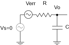
To see these formulas come to life, let’s look at a simple example involving a signal chain that has just two stages: (1) A sensor stage consisting of an ideal voltage source, and (2) a low-pass filter stage.
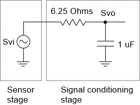
To compute required sensor power, we need to know the gain, input impedance, and noise voltage of the low pass filter. We’ve covered these in other Short and Sweet articles, here, here, and here. The relevant formulas are shown below in \(\displaystyle j\omega \) form:
\(\displaystyle G(s)=\frac{1}{{1+RCs}}\quad \Rightarrow \quad G(j\omega )=\frac{1}{{1+j\omega RC}}\)
\(\displaystyle InZ(s)=R+\frac{1}{{Cs}}\quad \Rightarrow \quad InZ(j\omega )=R+\frac{1}{{j\omega C}}\)
\(\displaystyle {{N}_{v}}=\sqrt{{{{KT}}/{C}\;}}\)
Suppose we have R=6.25 Ohms, C=1μF. This gives the filter a corner frequency of
\(\displaystyle {{F}_{c}}=\frac{1}{{2\pi RC}}=25.465\,kHz\).
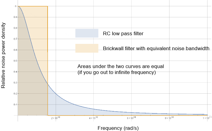
Its effective noise bandwidth, that you saw how to compute here, is
\(\displaystyle ENBW=\frac{\pi }{2}\times 25.465\,kHz=40\,kHz\).
Suppose we’d like to find the SNR in the flat part of the filter’s curve, say at 1 kHz. That will be our frequency of interest (FOI), and from that we can compute \(\displaystyle j\omega \):
\(\displaystyle j\omega =j2\pi f=j2\pi \times 1\times {{10}^{3}}=6.2832\times \ {{10}^{3}}rad/s\)
UPDATE: Earlier versions of this post used an FOI of 10 kHz. We changed to 1 kHz to be further into the flat part of the gain curve.
Plugging all this in we get the following at 1 kHz:
\(\displaystyle \left| {G(j\omega )} \right|=\left| {\frac{1}{{1+j\omega RC}}} \right|=\left| {\frac{1}{{1+j6.2832\times {{{10}}^{3}}\times 6.25\times 1\times {{{10}}^{{-6}}}}}} \right|=0.99923\)
\(\displaystyle InZ(j\omega )=R+\frac{1}{{j\omega C}}=6.25+\frac{1}{{j6.2832\times {{{10}}^{3}}\times {{{10}}^{{-6}}}}}=6.25-159.155j\)
Notice the minus sign in the imaginary part of this impedance. That minus sign implies that the impedance — which is the sensor load, is capacitive in nature. You’ll see this come into play later.
Now, suppose we’d like an SNR equivalent of 24 bits of resolution. You saw in an earlier Short and Sweet article how to compute a signal to noise ratio using ENOB. Here’s the non-dB version of the formula:
\(\displaystyle SNR={{2}^{N}}\sqrt{{{3}/{2}\;}}={{2}^{{24}}}\sqrt{{{3}/{2}\;}}=20,547,809\)
That’s right. To get 24 bits of resolution, you need a signal that is over 20 million times stronger than the noise in the system. Let’s compute the noise voltage now, assuming the temperature is 290 degK:
\(\displaystyle {{N}_{v}}=\sqrt{{{{KT}}/{C}\;}}=\sqrt{{1.38\times {{{10}}^{{-23}}}\times 290/{{{10}}^{{-6}}}}}=63.26\,nV\).
From this, we can compute the signal chain output voltage at 1 kHz as:
\(\displaystyle {{S}_{{vo}}}=SNR\times {{N}_{{vo}}}=20,547,809\times 63.26\times {{10}^{{-9}}}=1.3\ Vrms\)
Now we can compute the required input voltage, and then, using the system’s input impedance, the required signal power, all at 10 kHz:
\(\displaystyle {{S}_{{vi}}}=\frac{{{{S}_{{vo}}}}}{{\left| {G(j\omega )} \right|}}=\frac{{1.3}}{{0.99923}}=1.301\ Vrms\)
\(\displaystyle {{S}_{{pi}}}(j\omega )=\frac{{{{S}_{{vi}}}^{2}}}{{{{{\left| {G(j\omega )} \right|}}^{2}}}}\times \frac{1}{{InZ(j\omega )}}={{1.301}^{2}}\times \frac{1}{{6.25-159.155j}}=0.000417+0.01063j\)
Taking the magnitude of this will give us the apparent power, which comes in at 10.64 mVA. The real and reactive powers come in at 417 uW and 10.63 mVAR, respectively. The sensor power has a large reactive component, so the power factor will be on the small side. It comes in at:
\(\displaystyle \text{Power factor}=Sgn({Im}(InZ(j\omega )))\times \frac{{\text{Real power}}}{{\text{Apparent power}}}=(-)\frac{{0.00042}}{{0.0106}}=-0.0392\)
Per our local conventions, we’ve given the power factor a minus sign to signify that the required power is delivered to a capacitive load.
What does this mean?
We noted earlier that our low-pass filter had a 40 kHz effective noise bandwidth. And we note that to achieve 24-bits of resolution, we need a signal power of at least 10.64 mVA. You’ll be interested to note that this required apparent power is the same no matter what value is used for the resistance (as long as the capacitance is correspondingly changed to keep the filter at 40 kHz effective noise bandwidth, and we stay with a 1 kHz signal.) You’ll see this come to life in Part 2.
We think this is an interesting result. A 40 kHz bandwidth is not too far off from what a simple system to digitize audio might have. It tells us something general about what it takes to achieve 24 bits of resolution in such an analog to digital signal chain — assuming that you are using a straight forward A/D converter that does not use over-sampling. We mentioned in the previous article on ENOB that the formulas we’re using here assume no over-sampling.
What’s the impact of this result? We’re not sure — but we note that armed with the formulas above, such thought experiments are possible.
Summary
In this article we derived the formulas for computing the required sensor power (and voltage and current) at a given frequency for a desired SNR and a given signal chain. You should note that these formulas are built-in to Signal Chain Explorer. We know of no other tool that computes these numbers for you so easily. In fact, we know of no other tool that even talks about them at all! We think they will be invaluable to you — they give you insights into just what it takes to achieve a high resolution signal. You’ll most likely be surprised when you move to resolutions higher than 16 bits. You’ll see that things can quickly get out of hand — and Signal Chain Explorer will show you just out of hand that can be. You’ll learn to appreciate taking charge and controlling the noise in your system. You’ll see examples of this in Part 2 of this Short and Sweet article.








 Parallel RC version