Required Sensor Power – Part 3
In Parts 1 and 2 of this series on required sensor power we introduced you to the formulas needed to compute this power, and you got to see the formulas in action in Signal Chain Explorer. At the end of Part 2 you saw that a high resolution output, even with an extremely simple signal chain of just a sensor and low pass filter, can be hard to achieve. The required voltage, and especially the required power, shoots up quickly.
In this article, we continue on with our exploration of sensor power. We start with the notion that maybe one way to reduce the sensor power requirements is to buffer the signal. Maybe by letting the buffer draw its own power we can reduce the sensor power requirements.
Recall from Parts 1 and 2 that our low-pass filter had a 25.465 kHz corner, using R=6.25 Ohms, and C=1uF. We’ll use this filter throughout this article, and we’ll be using a signal frequency of interest of 1 kHz.
NOTE: In this article — and most articles presented on this site, we are doing mathematical thought experiments, playing “what-if” games when it comes to finding the limitations of a signal chain. Signal Chain Explorer uses linear-system math and therefore can’t model problems such as non-linear clipping and over-voltages very well. But that’s not necessarily bad. In our thought experiments, we are trying to see what the math tells us would be required to get the results we want. We get hypothetical results pretending that devices can handle any currents and voltages we throw at them, even though in the real world, these might cause chips to fry and wires to melt. We are more concerned in our thought experiments about noise and interference and the effects these have on our systems. It’s implied that any solutions you settle on should ultimately be checked against real-world device limitations.
Perhaps a Unity Gain Buffer?
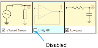
Okay, then. Let’s get started. We’ll begin by using the simplest buffer of all — a unity gain buffer, placing it between the sensor stage and the low pass filter stage. But we’ll make the buffer disabled at first. This means it doesn’t exist as far as the simulation is concerned. We have just the sensor stage and the low pass stage. That gives us our starting baseline.
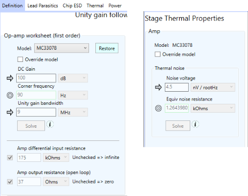
For this unity gain buffer, we have carefully chosen a suitable op-amp. We have two main criteria: (1) We’d like low noise, because that will be mean less output voltage required to make up for that noise, which in turn keeps the power requirements down, and (2) the rather large 1 uF capacitor in the low pass stage with a small resistance of 6.25 ohms means we have a capacitive load on the amp stage. This can cause peaking that we probably don’t want. One way to get around this is to select an op-amp with low output resistance. Thus, we choose the MC33078 op-amp from the SCE built-in database, which has a reasonable 4.5 nV / root Hz of noise, and an output resistance of 37 Ohms.
But First, Establish a Baseline
Okay, with the proper op-amp selected, we disable the unity gain buffer stage temporarily, and, using the Required Sensor Power dialog, we’ll set the system for 24 bit resolution to get our baseline. The results — remember, for 1 kHz — are:
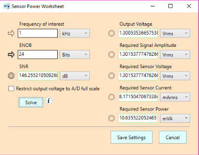
We see that a 1.3 Vrms output voltage is required, which corresponds to roughly the same input voltage, and a sensor current of 8.17 mArms. The sensor power is just over 10.6 mVA. These are the same results we saw in Parts 1 and 2.
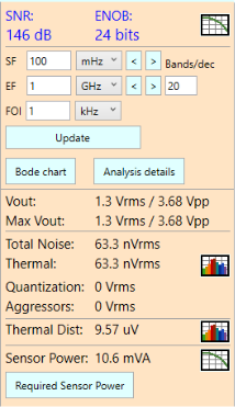
As you learned in Parts 1 and 2, the resulting values are needed to produce an output voltage that will counteract the 63.3 nVrms of thermal noise caused by the resistor in the low pass filter, as we can see from the results panel:
Results with a Unity Gain Buffer
Next, let’s enable the unity gain buffer and see how that changes things. Will it cause the sensor power to drop?

Let’s run the Required Sensor Power worksheet for 24 bits and find out:
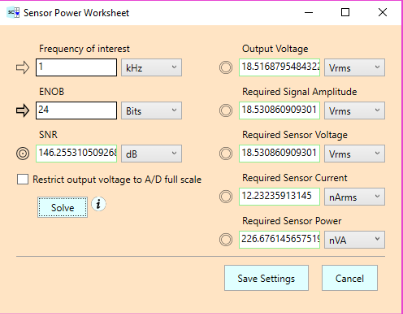
As we suspected might happen, the required sensor power drops dramatically, from 10.6 mVA to 227 nVA — roughly a 50,000 to 1 one reduction. This is due to very little current being drawn by the input pin of the buffer (which has an input resistance of 175 kOhm). And we do in fact see that the sensor current has dropped from 81.7 mArms to 12.2 nArms.
It’s a win, right?
Not exactly. Our reduced power comes at a cost: The required sensor voltage shoots up from 1.3 Vrms to 18.5 Vrms — an order of magnitude increase. Why? It turns out, we need the extra voltage to counteract additional noise in the system, up from 63.3 nVrms to 901 nVrms, as seen in the updated Results Panel:
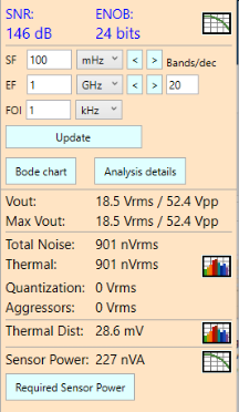
Where did this extra noise come from? It’s thermal noise in the op-amp stage, as illustrated in the thermal noise plot:
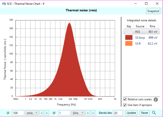
The op-amp contributes 901 nVrms of thermal noise, swamping out the 63.2 nV of thermal noise in the low pass filter resistor.
Note that the op-amp was specified to have a thermal noise density of 4.5 nV / root Hz. This is a reasonable spec for the thermal noise of an op-amp. But it costs us anyway.
Perhaps Add Amplification?
Maybe if we add gain to our buffer we won’t need such high input voltage. Maybe we can let the higher output voltage due to the gain counteract the noise. We can try this by deleting the unity gain buffer stage and then adding a voltage gain follower (aka non-inverting) stage in its place.
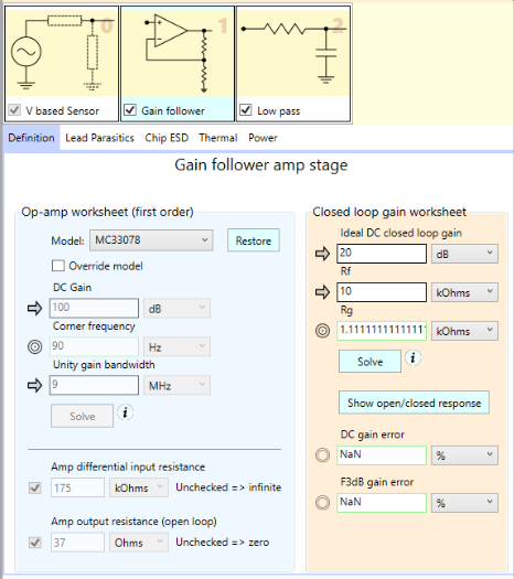
With the exception of switching to the MC33078 op-amp, we’re using the default parameters for this stage, including 20 dB of gain. We note in particular the default Rg value (the resistor to ground branching off the feedback network) of 1.1 kOhms. That’ll come to bite us as you’ll soon see.
Let’s run the Required Sensor Power worksheet, again for 24 bits:
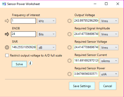
Our required signal amplitude increases from 18.5 Vrms to 24.4 Vrms, and the current shoots up from 12.2 nArms to 161.7 nArms. This makes our power increase from 227 nVA to 3.95 uVA. And look at the output voltage. It goes up from 18.5 Vrms to a whopping 244 Vrms.
Ouch!
What happened?
Well, the op-amp stage has a lot more noise than before, partly because that noise is now amplified when referred to output, and because of the resistors in the feedback network which contribute additional noise themselves. The overall noise has shot up from 901 nVrms to 11.9 uVrms. The thermal noise plot tells the tale:
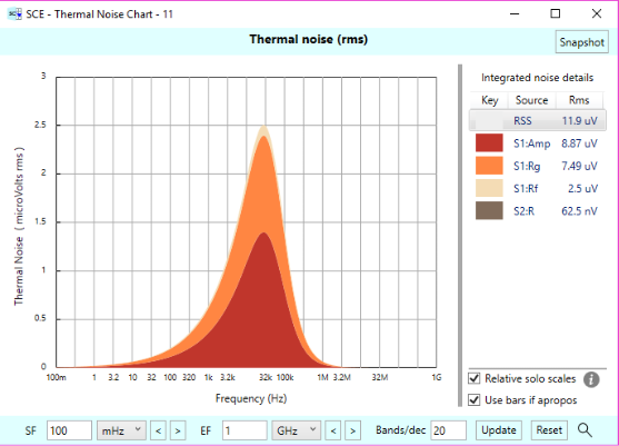
While the op-amp itself is still the main noise contributor, the Rg resistor — the resistor to ground off the feedback network — is a big contributor as well. And it contributes three times the noise that the Rf (the feedback resistor itself) contributes, even though Rf is a much bigger resistor (10 kOhms) than Rg (1.1 kOhms). You might be surprised by this, but it’s all due to what happens to the noise contributions as they are referred to output. It’s beyond the scope of this article to show why Rg is the bigger problem even though it’s a much smaller resistor — we’ll save that for another article, but the cool thing about Signal Chain Explorer is that it illuminates these issues for you with little effort on your part.
Keep the Noise Down, Bud!
Let’s see if we can help things along by reducing Rg, say to 10 Ohms. We’ll keep the same gain as before, so that means Rf must be reduced as well. We’ll let the equation worksheet do that for us by making Rf the target field (meaning it gets recomputed). So the new values look like:
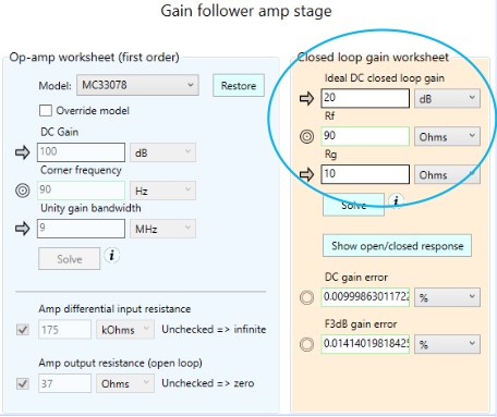
If we re-run the Required Sensor Power worksheet for 24 bits, we get:
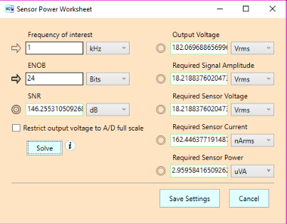
Our power requirements have been reduced from 3.95 uVA to 2.96 uVA. A modest improvement, but even so, we’ve come a long ways from the 10.6 mVA we had originally without any buffering at all. Unfortunately, though, we’ve gone backwards from the results we obtained with a unity gain buffer. With that, we only needed 226 nVA.
Amplifying the signal has come at a great cost. Our voltage requirements are through the roof. Whereas unbuffered we only needed 1.3 Vrms of sensor voltage, we now need 18.2 Vrms, which by itself may not seem too bad, but the output voltage is just ridiculous: 182 Vrms. It would be completely impractical to hook this up to an A/D converter. That’s a huge voltage for such a device to handle. Even the sensor voltage of 18 Vrms is bad enough.
We’re having all these problems because of the added thermal noise of the amp stage. That’s the price we pay for amplification. And that price is due in part to the required resistors in the feedback network — if we want a gain greater than one.
Homework: Further Optimizations — Down to 10.9 nVA
Now, we didn’t try optimize the thermal noise of our buffer stage to its ultimate bounds. For example, it might be possible to select an op-amp with very low noise, say, 1 nV / rootHz, maybe even a bit lower. (For this thought experiment, you could keep the MC33078 specifications, but with its noise modified from 4.5 to 1 nV / root Hz.) With the 20 dB gain stage, you’ll see the sensor power requirements drop dramatically to 166 nVA — from the 2.96 uVA we had last. But the output voltage is still going to be around 43 Vrms. By using just a unity gain buffer with this low noise op-amp, things are much better: 4.26 Vrms output, and 10.9 nVA of required sensor power. This is very reasonable. Not having a feedback resistor network is a big plus.
We’re not showing you screenshots of these experiments here. We leave these as avenues for you to explore for yourself using Signal Chain Explorer.
Another way to control noise is to reduce the bandwidth of the system — say by dropping the low pass filter corner from 25 kHz to 2.5 kHz, or whatever. This should reduce the thermal noise. We’ll again leave that up to you to explore. We do caution that if you do this, pay attention to what your frequency of interest is. You’ll most likely want to lower it so it stays in the flat part of the gain curve. And be careful of any peaking which may throw off your results. Keep an eye on the Bode Plot.
Bottom Line: Amplification with high resolution is hard to do!
In this Part 3 of our sensor power series, we explored what happens if you try to reduce the power requirements of the sensor by using a buffer, but still demand a high resolution. We’ve seen that, yes, with the buffer you can reduce the power requirements dramatically, but it comes with an equally dramatic cost if you don’t pay attention to thermal noise. The thermal noise goes up due to the added op-amp noise and also any feedback network resistor noise, and in trying to counteract this noise, the required output voltage shoots way up. In the amplified case, the voltage is so high it’s really impractical if you are wanting to digitize the signal. For the unity gain case, we can get reasonable results.
If you want high resolution — such as 24 bits — you must pay close attention to the thermal noise in your system. And we haven’t even mentioned having gargoyles (yes, our word for interference such as EMI and what not) added to the mix. Those will cost you even more.
Comments
Required Sensor Power – Part 3 — No Comments
HTML tags allowed in your comment: <a href="" title=""> <abbr title=""> <acronym title=""> <b> <blockquote cite=""> <cite> <code> <del datetime=""> <em> <i> <q cite=""> <s> <strike> <strong>