A new tool for embedded system designers
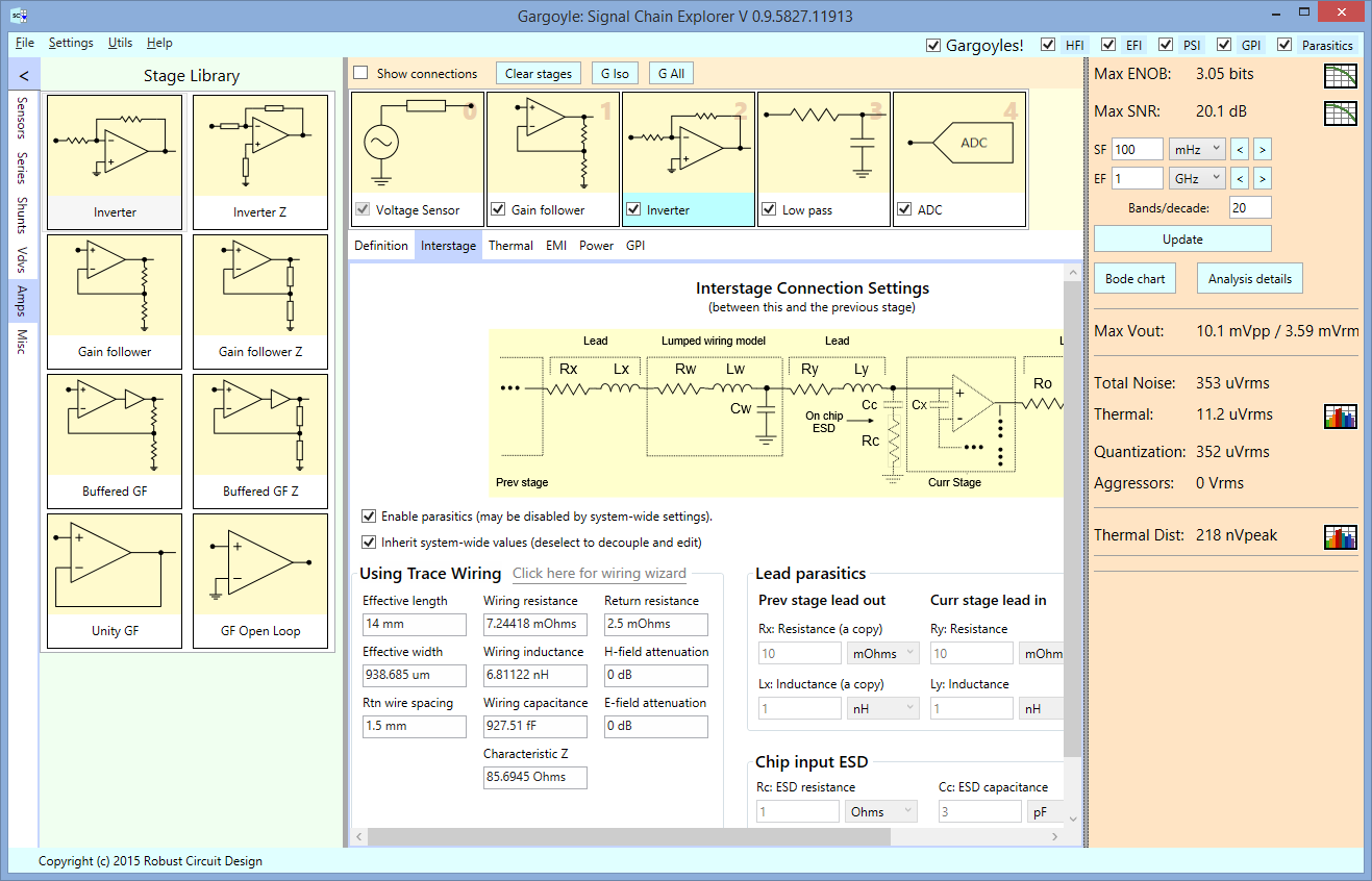
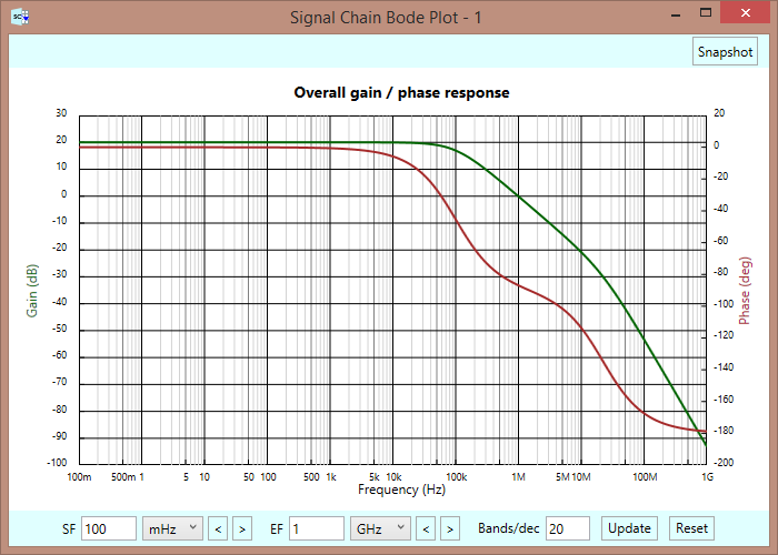
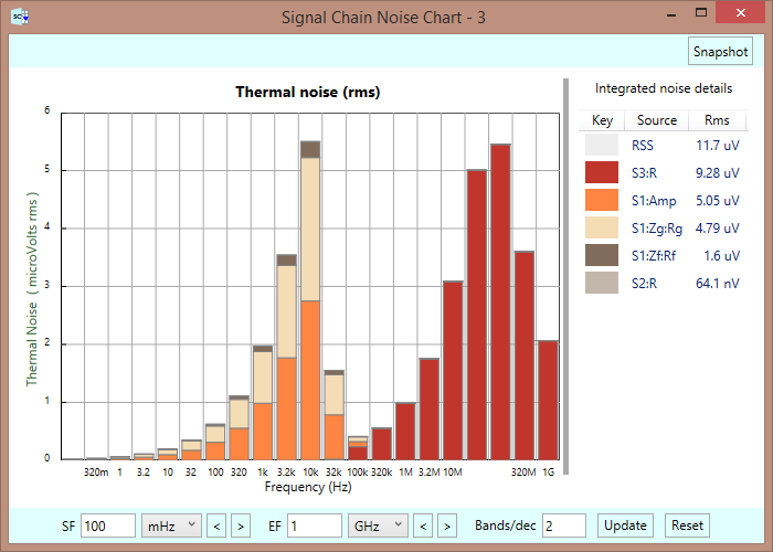
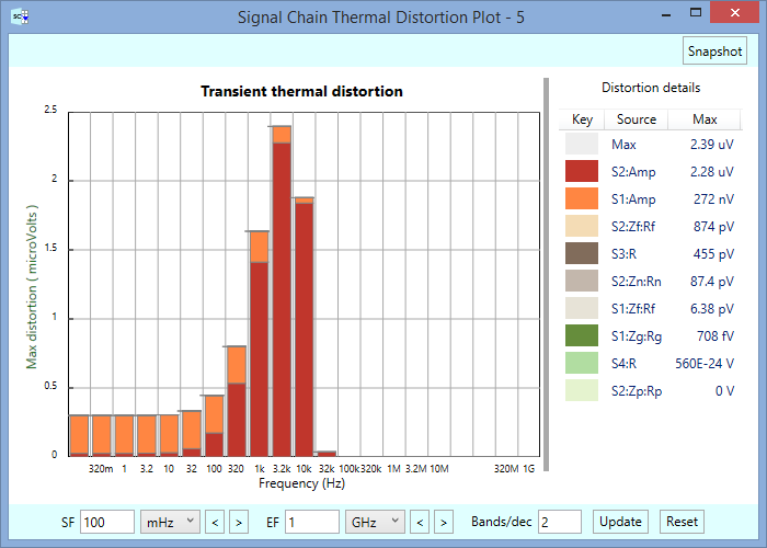
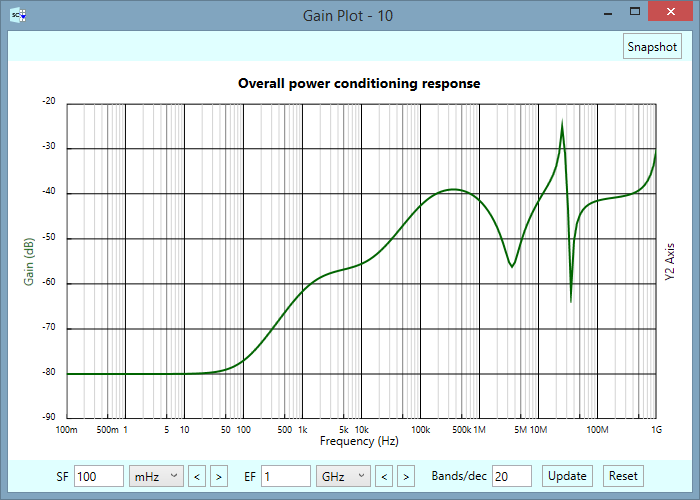
Signal Chain Explorer (SCE) is a software tool that helps you, the embedded system designer, explore the design space of an analog signal chain — the circuitry that goes from sensor to analog-to-digital (A/D) converter. The main goal of SCE is to compute the effective number of bits (ENOB) and signal-to-noise ratio (SNR) of the signal chain, and to account for all the things that affect these numbers, such as thermal noise, thermal transient distortion, electromagnetic interference, power supply and ground path fluctuations, connection wiring parasitics, peaking, and oscillations.
Featured in SCE is easy signal chain construction, easy parameter and equation entry, fast and accurate calculations, fast charting, and a built-in set of common interferer models used to trip up the unwary. All of this to aid you in determining quickly and easily what problems your signal chain may have, and then help you in finding workarounds and exploring the boundaries of what’s possible. Doing this kind of work in preliminary design will help lead you and your company to successful outcomes.
What is a signal chain, anyway?

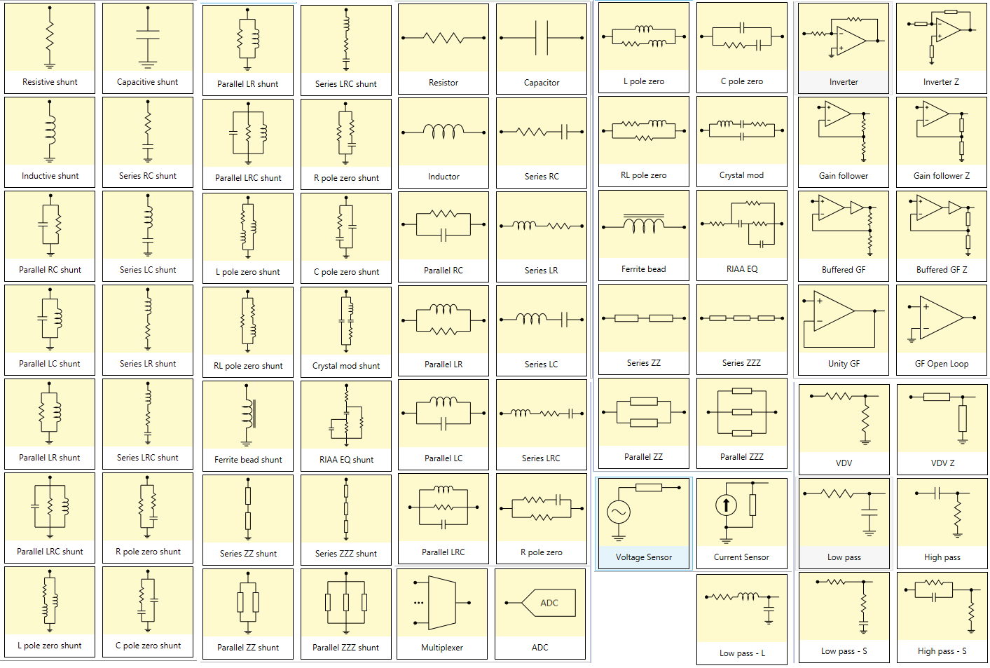
A signal chain is that part of your analog circuit that comprises the main path of your signal, from input sensor to output A/D. The chain is represented as a series of stages — each stage comprising a chunk of circuitry serving some functional purpose. Taken as a whole these stages make up the components you use to condition your signal for proper digitization. Examples include low pass and high pass filters, multiplexors, shunts, series branches, and closed-loop gain stages. The sensor and A/D converter are also treated as stages.
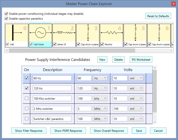
Not included in the signal chain are all the ancillary bits of circuitry that help support your signal path — things like power supply regulation, protection circuitry, control switches, and the like. (We do help you model local power isolation for your stages, but not the power bus itself.)
Why the gargoyle term?
![]()
The term gargoyle was first associated with the decorative water spouts on the sides of early medieval churches that often came in the form of grotesque creatures carved as stone figures. Some say these creatures, these gargoyles, were placed to ward off evil spirits. Others say the creatures were there to remind the lay people that evil lurks everywhere, and to be wary.
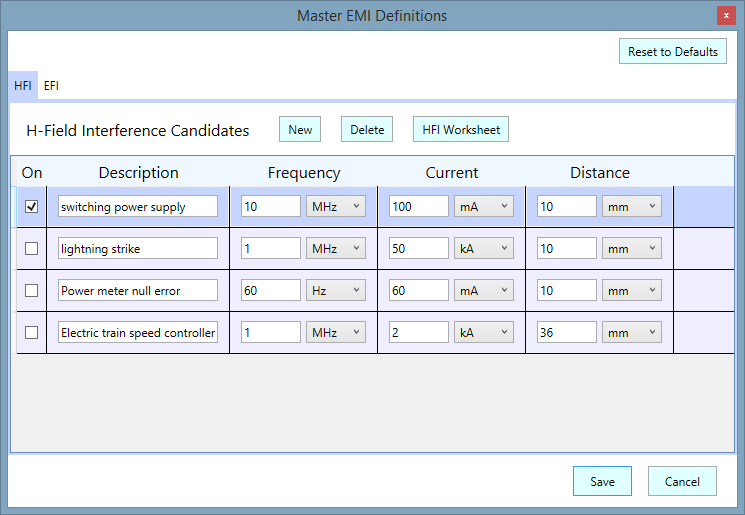
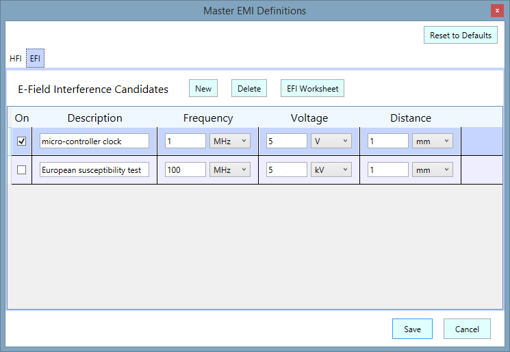
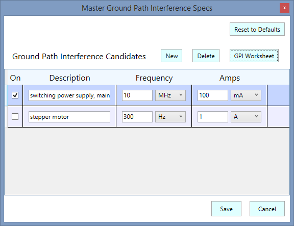
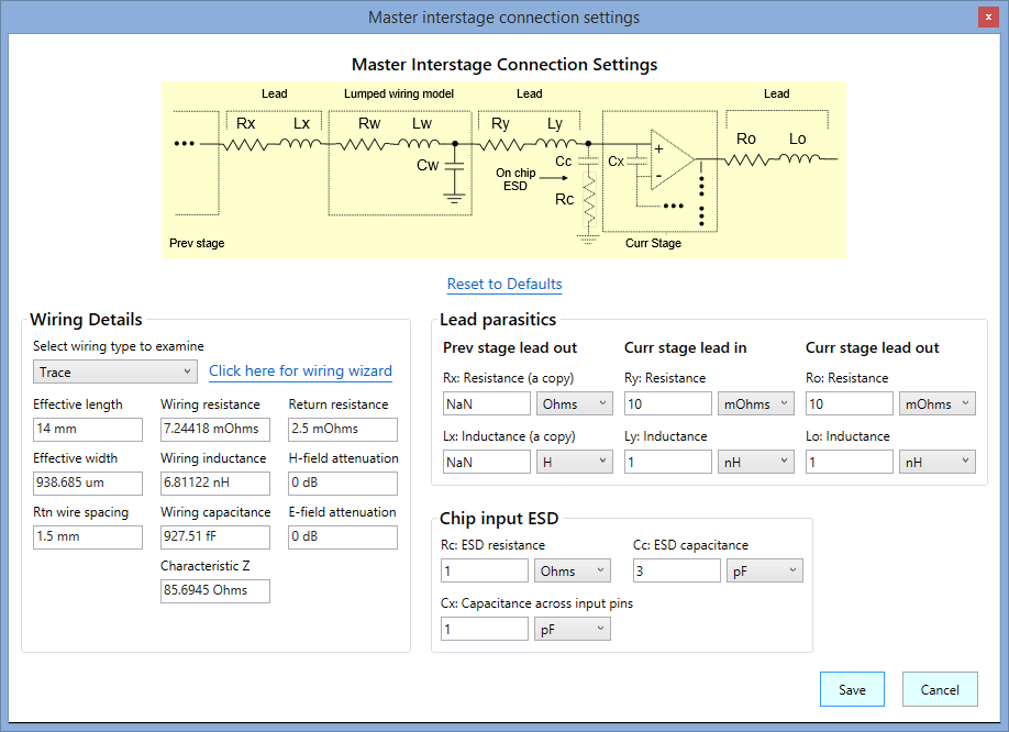
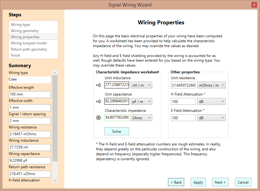
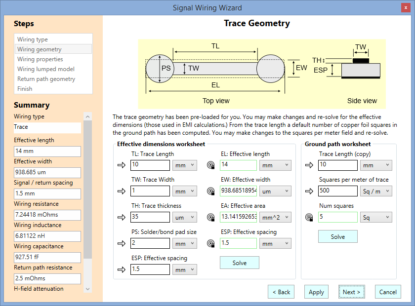
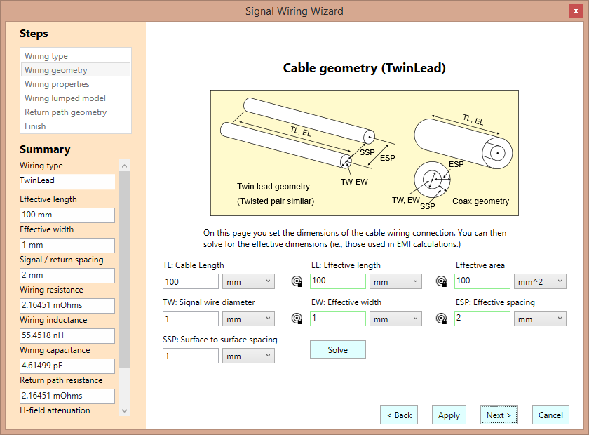
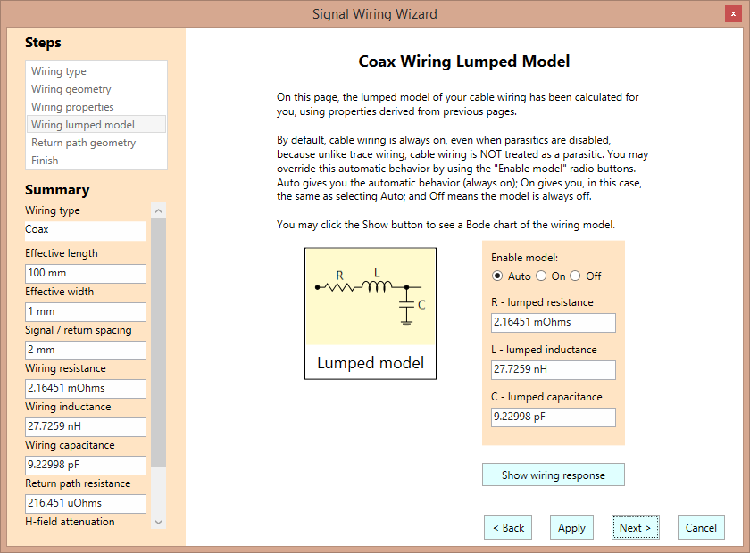
It’s in the latter spirit that we use the term gargoyle. In SCE, gargoyles are those aspects of your circuit that can wreak havoc, causing a loss in signal quality and causing unwanted oscillations. Examples include capacitive loads on op-amps that cause peaking, parasitics in trace wiring or cables, thermal noise, thermal transient distortion, and last but not least, interference from stray H-field and E-fields. An example of the latter might be the interference caused by placing a microprocessor clock line too close to the main signal line — a scenario that’s easy to encounter in an embedded system, if you aren’t careful.
The main purpose of SCE is to help you track down and capture the gargoyles in your embedded system — to find the lurking gremlins who are otherwise ready to pounce on the unwary circuit designer.