Upgrades to the Sensor Stages in Signal Chain Explorer
The most recent versions of Signal Chain Explorer (SCE) have seen upgrades to the sensor stage library. SCE now has three types of sensors, all general in nature, and all meant to allow you to model a variety of basic sensor configurations by choosing appropriate parameters. The three types are:
- Voltage based sensors
- Current based sensors
- Charge based sensors
In this post, we give an overview of these sensor types. We hope to have articles that go into more detail in the future.
NOTE: While the current crop of sensors have only single-ended outputs, we are working on sensor stages with differential outputs, but they’re not ready yet. Also, the three sensor types given here form the nucleus of more complex and specific configurations. We’ll be adding more sensor stages along these lines as times goes by.
Voltage Based Sensors
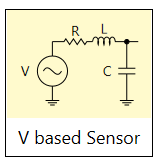
A voltage based sensor has a voltage source as its input signal. For convenience, you can optionally specify a series resistance, series inductance, and a capacitor shunt to ground. Next, we’ll show a few examples.
Guitar Pickup
A guitar pickup can be modeled using a voltage based sensor stage. Such a pickup has one or more bobbins of wound wire surrounding magnetic poles, usually one per string, and the pickup works by magnetic induction. Vibrating guitar strings cause a voltage to be generated in the pickup. A typical voltage range is in 100s of millivolts to a volt or so. In simple models of a guitar pickup, all three types of impedance are present: series resistance, series inductance, and shunt capacitance. In these simple models, the pickups have two poles in their response (they are second order). Because of this, they exhibit a resonant frequency. Below is an example of a Stratocaster type guitar pickup:
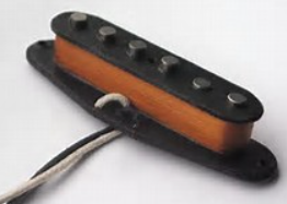
Here’s how we might model this in SCE:
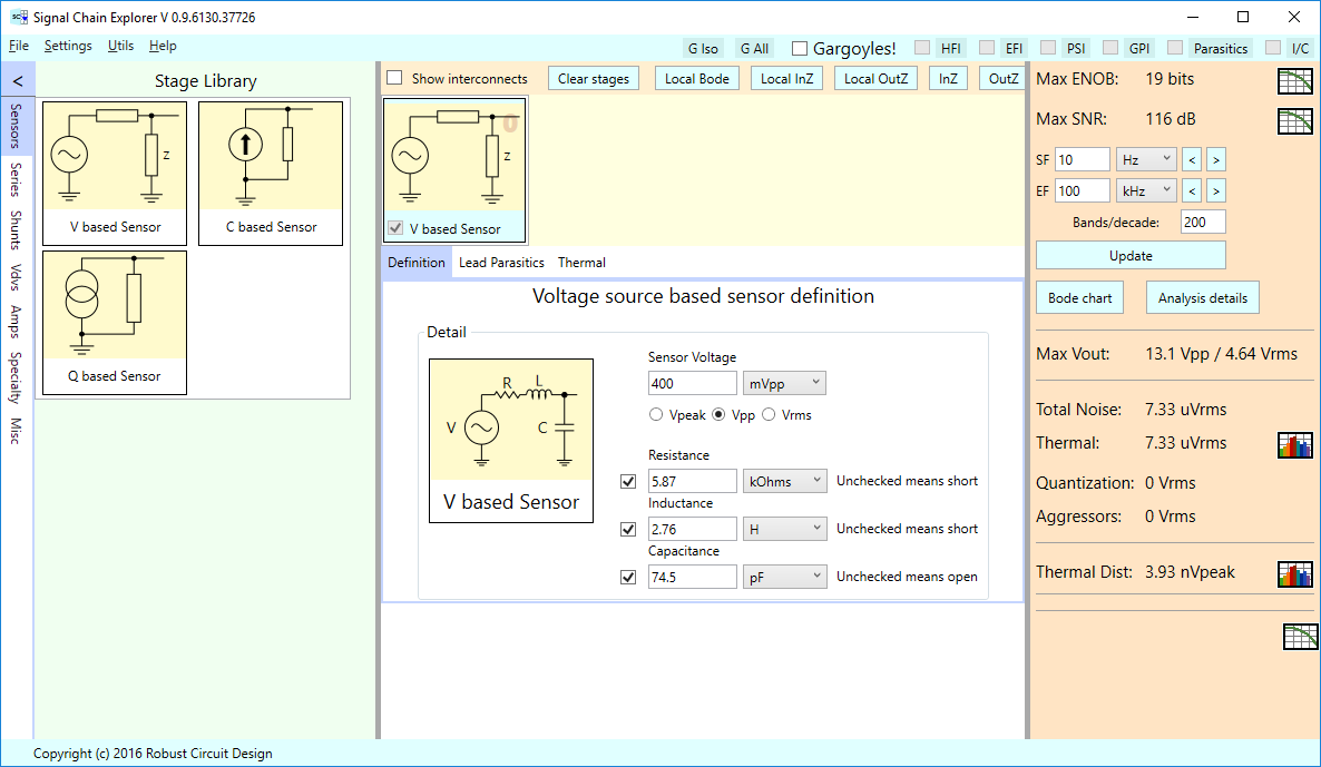
We’ve arbitrarily set the input voltage to 400 mV, but it’s not a bad place to start for such a pickup.
NOTE: For all sensors stages of SCE, we pretend the specified signal voltage applies for any signal frequency we happen to use during the frequency sweeps of the simulation.
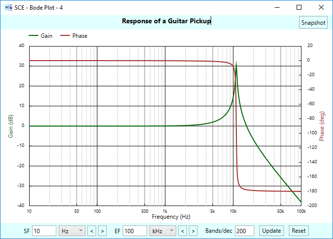
Here’s a bode chart that shows the second order response of our pickup, which has a resonant frequency around 11 kHz. Most guitar pickups resonate in the 5-15 kHz range, and it’s common for electric guitars have tone circuits and controls to help tame this resonance and shape the characteristic sound of the guitar. Proper specification of cables, termination shunts, etc, come into play for this as well.
Phono Cartridge
Another example of a voltage based sensor is a phono cartridge pickup, which involves a magnet and a coil. Either the magnet or the coil moves due to needle vibrations. Here, we’ll show an example of a moving magnet cartridge — a Shure M97xE.
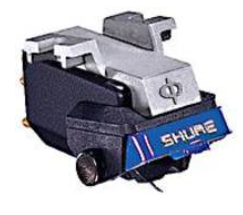
This cartridge generates on the order of 4 mV peak (depends of course on the passage of music), and the cartridge has both series resistance and inductance, as shown in the following stage definition in SCE:
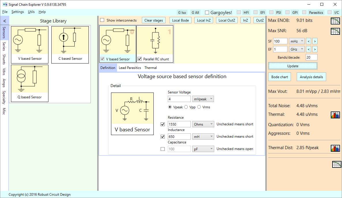
The Shure M97xE spec sheet shows the cartridge having 1550 ohms of series resistance, and 650 mH of inductance. No capacitance value is specified, so in the stage definition, we have unchecked the capacitor entry. This has the effect of leaving the shunt branch open.
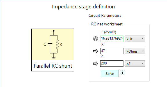
Phono cartridges must be properly terminated. A typical thing to do for these types of cartridges is to terminate them with a parallel resistance and capacitance shunt, using 47 kOhms and several hundred pF (some of which might be in the wiring from the cartridge to the termination shunt.) Here is the definition of a typical phono cartridge shunt stage in SCE:
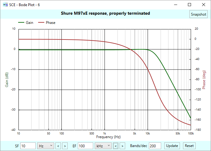
Below is the bode chart of the cartridge and termination shunt. Properly terminated, no peaking is exhibited in the response, even though we have a second order system with both inductance and capacitance. There is about 6 dB of rolloff at 20 kHz, and thereafter starts the 40 dB/decade rolloff indicative of a second order system.
Current based sensors
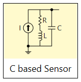
A current based sensor has a current source as its input signal. Rather than have a series-shunt voltage divider configuration to model the sensor impedance, we use two parallel branches instead.
Photo Detector / Transimpedance Amplifier Circuit
An example of a current based sensor is a photo detector diode. We can model this type of detector as a current source with a parallel capacitor as shown in the following photo detector / transimpedance amplifier circuit, borrowed from the Microchip datasheet for their MCP6021 device:
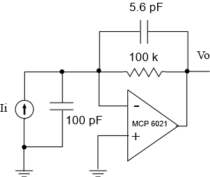
This transimpedance circuit converts the input current Ii into output voltage Vo.
Here’s how we can model this in SCE. We split the circuit into two stages: a current based sensor stage, and an inverting amplifier stage. Below we show the definition for the sensor stage:
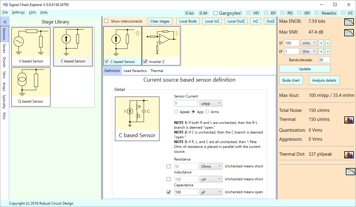
Though the current based sensor stage allows for a series R-L branch, we aren’t using one here.
A note on how the R, L, C parameters work (they work similarly in the other sensor stages): Left unchecked, the resistor is treated as being a “short” having zero resistance. An unchecked inductor is also treated as a “short’ having zero inductance. If both resistor and inductor are left unchecked, SCE interprets this configuration to mean the whole R-L branch should be “open” — that is, it’s not there at all.
We do keep the capacitor shunt, though, and we’ve given it a value of 100 pF as per the Microchip circuit. If we hadn’t checked the capacitor field, the capacitor branch would be treated as “open” as well, and we’d end up with a naked current source having an infinite output impedance. In such cases, SCE automatically and implicitly adds 1 PetaOhm of parallel resistance to model this “infinite” impedance.
We’ve arbitrarily set the input signal current to 1 uA. As before, this signal amplitude is used for all frequencies in the simulation.
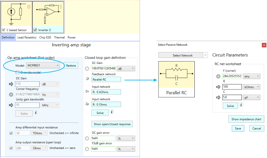
Below is the definition of the amplifier stage as implemented in SCE. We use a “generic” inverter stage — generic in that it allows us to use arbitrary passive networks for the input, feedback, and ground path impedances. Here, the input and ground path impedances are defined shorts, as per the circuit above, and the feedback path is a parallel RC, which is defined by popping up the dialog as shown on the right. We’ve also used the built-in op-amp database of SCE and selected the MCP6021 amplifier model:
Here is the bode chart for the sensor-plus-transimpedance amplifier circuit. Note the “gain” defined here is not a ratio of output to input voltages, but rather, is the transimpedance — the ratio of output voltage to input current.
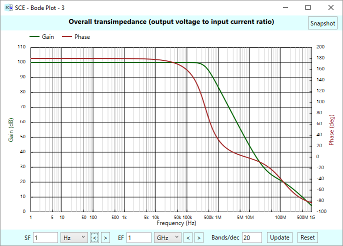
Due to careful selection of parameter values, we have a nice flat response out to 200 kHz, with no evidence of peaking.
Charge based sensors
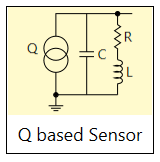
The charged based sensor stage of SCE is similar in construction to the current based sensor stage, but uses a charge source rather than a current source. (Remember, current is the time derivative of charge, or vice versa, charge is the time integral of current.)
A piezo-electric sensor
A good example of a charge based sensor is a piezo-electric sensor. These sensors, either made of solid quartz or similar, or of manufactured ceramics, produce electrical charges when the sensor is squeezed, twisted, pressed, or otherwise distorted mechanically. Such sensors are quite versatile, and can be used as force or strain sensors, pressure sensors, accelerometers, and as acoustic pickups and percussion triggers. Quartz piezo-electrics can work at very high temperatures, making them ideal in many industrial/aerospace applications.
For our example here, we’ll be modeling a ceramic sensor — the Murata 7BB-35-3L0, which is a disk sensor as pictured below.
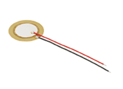
This sensor can be used as an acoustic pickup — or in the cases we’ve used it for, as a “percussion trigger” in an electronic midi drum kit.
There are various ways to model piezos. A simple method is to model it as a charge source in parallel with a capacitance, and you will see this quite often in the literature. We’ll also add a parallel resistance, which represents the “leakage” resistance in the sensor that determines the sensor’s output resistance at DC:

NOTE: This simple model does not capture any resonances in the piezo, but note that piezos do in fact resonate, and may have more than one resonant frequency. We’ll be showing a better model for piezos in later articles, but for now, just assume the sensor is being used in the flat region of its response, away from any peaking. This is a common thing to do in practice, but also note that in practice, not remembering that there is resonance may very well trip you up.
The Murata 7BB-35-3LO sensor has 30 nF of capacitance according to its datasheet. No DC resistance is given, but we’ll estimate, say, 20 MOhms. Most of these sensors have very high resistance values in the 10s to 100s of MOhms, and even GOhms and beyond. The Murata datasheet also shows a resonant frequency of 3 kHz that we’ll be ignoring for this blog post.
We define the piezo stage as follows in SCE:
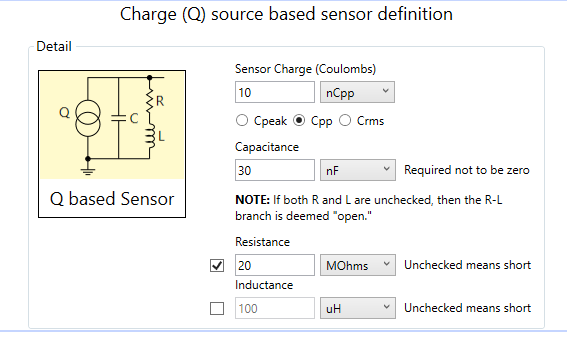
We leave the inductance unchecked, so it’s treated as a short.
NOTE: You’ll notice that there is no check box for the capacitor. This field is not optional. The reason for this is that SCE works by primarily using signal voltages as it goes from stage to stage. It cannot work directly with charges. What actually happens behind the scenes is that SCE converts the charge source and parallel capacitor into it a voltage source and series capacitor, reminiscent of a Norton to Thevenin conversion:

Having measured sensors like the 7BB-35 in the lab, we know that they can output 100s of mV quite easily by tapping on the sensor through a chunk of sanding block foam (to protect the sensor). To get an output voltage in this range, we’ll set the output charge to 10nC. How does this relate to 100s of mV? By the following equation, which uses the charge/voltage equation for capacitors:
\(\displaystyle \frac{q}{{{{C}_{p}}}}=\frac{{10\,nC}}{{30\,nF}}=333\,mV\)
NOTE: As usual with the sensor stages of SCE, we are going to pretend that the sensor outputs the same signal amplitude at all frequencies we might happen to sweep during simulation.
Because of the capacitance in the sensor and its relatively small output charge, using a piezo sensor in a circuit can be tricky, as cable capacitances and inductances can easily upset the measurements. This can be handled by using a “charge amplifier”, which mitigates the effects of such parasitics. An example of such a circuit is given below:
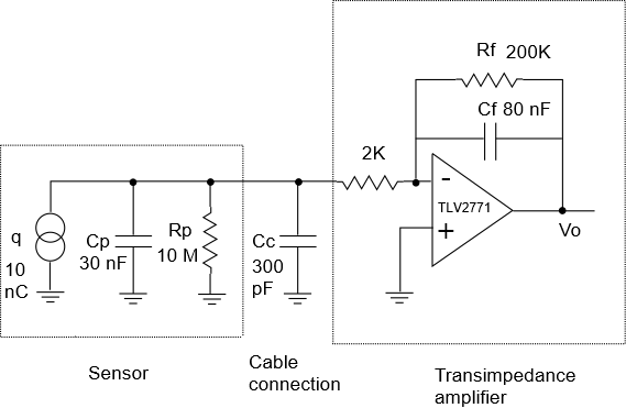
Here, we’re modeling a cable capacitance of 300 pF and then using an inverting amplifier stage with parallel RC feedback.
NOTE: SCE has a more sophisticated way to handle cable parasitics through its interconnect modeling. For sake of simplicity in this blog post, we’ll just directly model the cable as a capacitive shunt and leave the interconnect parasitics of SCE turned off.
The op-amp chosen is a Texas Instrument TLV2771, which we select from the built-in op-amp database.
We model the charge amplifier and how the signal chain in SCE as follows. We also show the Parallel RC popup dialog used for the amplifier feedback definition:
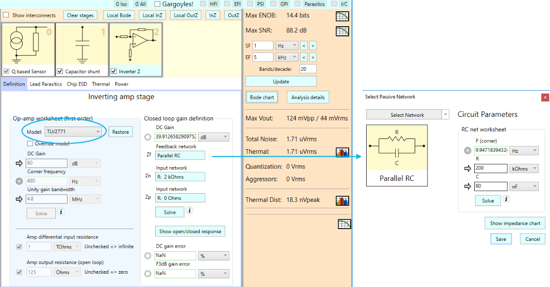
Next, let’s take a peek at the bode chart for this signal chain. As was the case with current based sensor stages, the bode charts for charge based sensors are actually transimpedance plots, in this case relating output voltage Vo to input charge q:
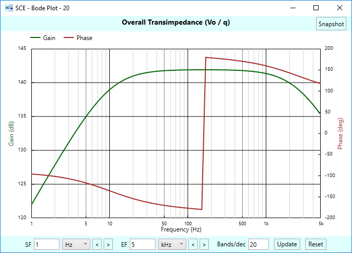
Charge amplifiers are cool because the maximum transimpedance gain (and thus the maximum output voltage) that occurs in the flat region of the response is directly controlled by the feedback capacitor Cf, and you can quite easily compute this voltage as follows, where our Cf is 80 nF:
\(\displaystyle Max\,voltage=\frac{q}{{{{C}_{f}}}}=\frac{{10\,nC}}{{80\,nF}}=125\,mV\)
Note from this formula that the only thing that matters, as far as the maximum output is concerned, is that you know the input charge and the feedback capacitor. Any nasty cable parasitics do not affect the result. That’s the major advantage of using charge amplifiers. In effect, you set the transimpedance gain solely by the value of the feedback capacitor. It should be pointed out, though, that this only holds in the flat region of the response — and you still need to worry about the frequency response in general. Don’t get complacent!
There’s plenty more we could discuss on the use of such charge amplifiers, but we’ll leave that for another day.
Conclusion
We’ve just scratched the surface on modeling sensors in SCE, and we’ve just scratched the surface in regards to the various complexities of using the sensors mentioned in this article. We hope to have more detailed discussions of these topics in future articles.
Comments
Upgrades to the Sensor Stages in Signal Chain Explorer — No Comments
HTML tags allowed in your comment: <a href="" title=""> <abbr title=""> <acronym title=""> <b> <blockquote cite=""> <cite> <code> <del datetime=""> <em> <i> <q cite=""> <s> <strike> <strong>