My KT lies over the C (Part 1)
My Bonnie lies over the ocean. My KT lies over the C …
Okay, with that lame joke out of the way, in Part1 of this (perhaps not so) Short and Sweet two-part article, we’ll derive the well-known \(\displaystyle {{\eta }_{v}}^{2}={{KT}}/{C}\;\) equation, relating thermal noise to first order circuits involving capacitors. In Part 2 we’ll test out the equation using Signal Chain Explorer. By doing this we can accomplish two things:
(1) We can confirm that the underlying thermal noise calculations used in SCE are indeed correct,
and
(2) we can better relate the noise voltage integration by comparing the thermal noise plots automatically generated in SCE with the actual circuit response.
Wait. Capacitors have noise? No, not really.
When it comes to noise involving capacitors, you may already be familiar with our featured formula:
\(\displaystyle {{\eta }_{v}}^{2}={{KT}}/{C}\;\)
where \(\displaystyle {{\eta }_{v}}\) is thermal noise voltage.
This formula seems to imply that capacitors have thermal noise. But that isn’t the case. Capacitors don’t have thermal noise (well, at least ideal ones don’t). Instead, the formula is meant to be applied only to certain circuits — first order networks with a resistance R and capacitance C. It really is the resistance that contributes the noise, but it just so happens that if you derive the thermal noise of that resistance and refer it to output, the resulting formula has the resistance cancelling out, and you are left with the famous KT/C equation.
In this article we’ll see how that comes about. To begin, we’ll start at ground zero and remind you of another famous formula for determining thermal noise power:
\(\displaystyle {{\eta }_{p}}=\frac{{{{\eta }_{v}}^{2}}}{{4R}}=KTB\quad \{W\}\)
or stated in terms of noise voltage,
\(\displaystyle {{\eta }_{v}}=\sqrt{{4KTBR}}\quad \{V\}\)
Here, K is Boltzmann’s constant, equal to 1.38064852e-23 J/degK, T is the temperature of the system, B is the bandwidth of the system in Hz, and R is the resistance.
NOTE: You might wonder where the factor 4 comes from. That’ll be explained in another article!
What is the bandwidth B of which we speak? We’ll get to that in a minute, but before we do, let’s remove it from our equation! We do this by dividing it out and coming up with noise power density, and its cousin, noise voltage density. These have units of \(\displaystyle {W}/{{Hz}}\;\) and \(\displaystyle {V}/{{\sqrt{{Hz}}}}\;\), respectively.
\(\displaystyle {{\eta }_{{pd}}}=\frac{{KTB}}{B}=KT\quad \{{W}/{{Hz}}\;\}\)
\(\displaystyle {{\eta }_{{vd}}}=\frac{{\sqrt{{4KTBR}}}}{{\sqrt{B}}}=\sqrt{{4KTR}}\quad \{{V}/{{\sqrt{{Hz}}\}}}\;\)
Now that we’ve removed bandwidth, let’s see why we should be concerned with it anyway! It turns out that thermal noise is random, in a Gaussian sort of way. (It should be noted that the power and voltage terms above are RMS values that relate to thermal noise’s statistical nature). Thermal noise is called white noise because it has the same RMS amplitude at all frequencies. (Well, at least up to the THz region.)
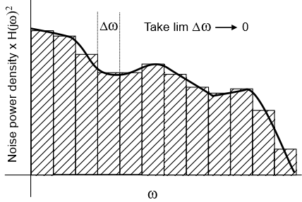
Any circuit that has resistance will have thermal noise, but due to the frequency response of the circuit, that noise will be modulated as a function of frequency. Let’s call that modulation function \(\displaystyle H(j\omega )\). We can plot the resulting noise power density vs frequency by using the square of \(\displaystyle H(j\omega )\), and then we can compute the overall noise power by chopping up the curve in the frequency domain into tiny slices and integrating. The figure below illustrates this process:

The area under this curve, that we get by integration, is the total noise power — an important value to know as it can greatly affect signal quality.
NOTE: We are using angular rad/s frequency above, even though the thermal noise power and voltage functions uses Hz. Don’t be confused. We’ll convert back to Hz when appropriate.
In dealing with the noise formula, it’s often useful to have a single bandwidth value to work with. We can define such a number, called the effective noise bandwidth, if we happen to know the total noise power for a given temperature and resistance — we just use an inversion of the KTB formula:
\(\displaystyle \text{Effective noise bandwidth }B=\frac{{{{\eta }_{p}}}}{{KT}}\quad \{Hz\}\)
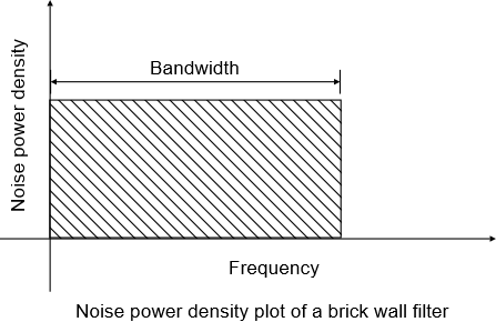
One way to think of this bandwidth is in terms of a brickwall filter. Such a filter has an output gain of one (that is, no attenuation) in its passband, and zero (complete annihilation) elsewhere. For a brickwall filter, the width of the passband is the effective noise bandwidth, by definition. The following plot illustrates:

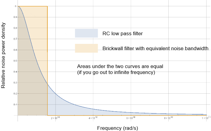
To determine the effective noise bandwidth of an arbitrary filter, the trick is to compute the area under the power density curve like we did earlier, and then find a brickwall filter that has the same area. The bandwidth of that brickwall will be our effective noise bandwidth. The figure below illustrates this for a low pass filter, along with its brickwall counterpart:

The bandwidth of the area in orange is the effective noise bandwidth of the low pass filter. In the example above, we’re using a low pass filter consisting of a 10 Ohm resistor and a 10 pF capacitor. This circuit has an effective noise bandwidth of 15.71 Grad/s (2.5 GHz). Next, we’ll see how to compute this.
Effective bandwidth formula
Given below is a formula for calculating the effective noise bandwidth of any filter utilizing noise power densities. It shouldn’t be too surprising, as we’ve already talked about integrating the density curve.
\(\displaystyle {{\omega }_{{enbw}}}=\int_{0}^{\infty }{{{{{\left| {\frac{{H(j\omega )}}{{{{H}_{{\max }}}}}} \right|}}^{2}}d\omega }}\)
Here, \(\displaystyle {{\left| {H(j\omega )} \right|}^{2}}\) is the absolute value of the filter’s noise power gain as a function of frequency divided \(\displaystyle {{{H}_{{\max }}}}\), its maximum. (In essence, we’re scaling to get relative power.)
To see this in action, we’re going to use this integral to calculate the effective noise bandwidth of a low pass filter. To do so, we’ll need to derive the thermal noise power gain function for that filter.
Noise power gain for a low pass filter
Given a thermal noise voltage associated with a resistor in a low pass configuration, let’s derive the value of that noise voltage referred to output. That will be \(\displaystyle {H(j\omega )}\), which represents how much that voltage is modulated at the output. Squaring that function gives us the noise power gain.
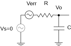
Here’s a diagram illustrating a voltage source and low pass filter. The thermal noise voltage generated by the resistor is represented by Verr, and we place it in series with the resistor. In this circuit, we set the source voltage to zero as part of the derivation for the referred-to-output noise voltage. This is in keeping with general circuit theory involving linear superposition:

What we’re looking for is the value of the output voltage Vo in terms of Verr, R, and C, and then we can take the ratio Vo / Verr. This gives us our desired gain function. We can derive this by using the voltage divider relation given below, where A is the generic series branch impedance, and B is the generic shunt branch impedance:
\(\displaystyle Vo=Verr\times \frac{B}{{A+B}}\quad \Rightarrow \quad H(j\omega )\equiv \frac{{Vo}}{{Verr}}=\frac{B}{{A+B}}\)
For a low pass filter, A = R, and B = 1/(C s) — the impedance of a capacitor in the Laplace domain. Plugging these values into our formula and staying in the Laplace domain, we can derive:
\(\require {cancel} \displaystyle H(s)=\frac{{{1}/{{\cancel{{Cs}}}}\;}}{{R+{1}/{{\cancel{{Cs}}}}\;}}\times \frac{{\cancel{{Cs}}}}{{\cancel{{Cs}}}}=\frac{1}{{1+RCs}}\)
Substituting \(\displaystyle s\to j\omega \), we end up with:
\(\displaystyle H(j\omega )=\frac{1}{{1+RCj\omega }}\)
For the effective noise bandwidth integral, we’ll be needing the noise power gain, which we can obtain by squaring the result we just obtained:
\(\displaystyle {{\left| {H(j\omega )} \right|}^{2}}={{\left| {\frac{1}{{1+RCj\omega }}} \right|}^{2}}=\frac{1}{{1+{{R}^{2}}{{C}^{2}}{{\omega }^{2}}}}\)
Note that at DC (\(\displaystyle \omega =0\)) we have maximum gain, so
\(\displaystyle {{H}_{{\max }}}={{\left. {\frac{1}{{1+{{R}^{2}}{{C}^{2}}{{\omega }^{2}}}}} \right|}_{{\omega =0}}}=1\)
Now we are ready to compute the noise bandwidth:
\(\displaystyle {{\omega }_{{enbw}}}=\int_{0}^{\infty }{{{{{\left| {\frac{{H(j\omega )}}{{{{H}_{{\max }}}}}} \right|}}^{2}}d\omega }}=\int_{0}^{\infty }{{\frac{1}{{1+{{R}^{2}}{{C}^{2}}{{\omega }^{2}}}}d\omega }}=\left. {\frac{{{{{Tan}}^{{-1}}}(RC\omega )}}{{RC}}} \right|_{0}^{\infty }\)
Evaluating our result at infinity and zero, and noting that \(\displaystyle {{Tan}^{{-1}}}(\infty )={\pi }/{2}\;\) and \(\displaystyle {{Tan}^{{-1}}}(0)=0\), we end up with:
\(\displaystyle {{\omega }_{{enbw}}}=\frac{\pi }{2}\frac{1}{{RC}}-0=\frac{\pi }{2}\frac{1}{{RC}}\)
In a first order RC system, the corner frequency is defined as
\(\displaystyle {{\omega }_{c}}=\frac{1}{{RC}}\)
With this, we can write the effective noise bandwidth as:
\(\displaystyle {{\omega }_{{enbw}}}=\frac{\pi }{2}{{\omega }_{c}}\)
This last formula is worth remembering anytime you need to know the effective bandwidth of your RC filter.
Final steps
Our effective noise bandwidth as just derived has units of rad/s. You’d have to convert to Hz to use it in the thermal noise equation. Here’s the derivation:
\(\displaystyle {{\omega }_{{enbw}}}=\frac{\pi }{2}{{\omega }_{c}}\)
\(\displaystyle 2\pi {{f}_{{enbw}}}=\frac{\pi }{2}{{\omega }_{c}}\)
\(\require {cancel} \displaystyle {{f}_{{enbw}}}=\frac{{\cancel{\pi }}}{2}{{\omega }_{c}}\times \frac{1}{{2\cancel{\pi }}}=\frac{{{{\omega }_{c}}}}{4}\)
Plugging in the formula for the corner frequency,
\(\displaystyle {{\omega }_{c}}={1}/{{(RC)}}\;\)
into the equation for \(\displaystyle {{f}_{{enbw}}}\), we obtain
\(\displaystyle {{f}_{{enbw}}}=\frac{{{{\omega }_{c}}}}{4}=\frac{1}{{4RC}}\)
With this last equation, we’re almost at the finish line, ready to derive the noise voltage for a low pass filter. All need to do is plug this formula for effective bandwidth into the formula for thermal noise power. That is, we set \(\displaystyle B={{f}_{{enbw}}}\). So we can write:
\(\require {cancel} \displaystyle {{\eta }_{v}}^{2}=4KTBR=\bcancel{4}KT\frac{1}{{\bcancel{4}\bcancel{R}C}}\bcancel{R}=\frac{{KT}}{C}\)
or
\(\displaystyle {{\eta }_{v}}=\sqrt{{\frac{{KT}}{C}}}\)
Voila! It’s magic! Our resistance R has disappeared. And we’ve managed to confirm that, yes, our KT really does lie over C.
Why does R disappear? Well, when R goes up, the noise voltage generated by R goes up too, but the gain function causes that voltage, referred to output, to be attenuated at lower frequencies than it would have otherwise. The effective noise bandwidth, used in deriving KT/C, encapsulates this balancing act.
In Part 2 of this Short and Sweet article, we’re going to put this formula to the test using Signal Chain Explorer. A key feature of SCE is that it computes thermal noise automatically. We can see if, for a low pass filter, we get the predicted results. The answer will be yes, and you’ll see that this formula works for other related RC circuits as well.
Comments
My KT lies over the C (Part 1) — No Comments
HTML tags allowed in your comment: <a href="" title=""> <abbr title=""> <acronym title=""> <b> <blockquote cite=""> <cite> <code> <del datetime=""> <em> <i> <q cite=""> <s> <strike> <strong>